TECHNICAL SPECIFICATIONS for Design and Development of Light Plants
List
of acronyms used in this document
EPOL-RC – Executive Point of Outdoor (Street) Lighting of Remote Control
FS – Feeding Station
TS – Transformer Substation
1 Purpose of EPOL-RC Feeding Station
1.1 Feeding station (FS) of EPOL-RC must be designed and developed for
application as a device for automatic, remote or manual control of street
lighting network and electric installations of alternating current with nominal
voltage of 220 V, with nominal frequency of 50 Hz, for distribution,
consumption metering and prevention of electric power theft, for protection of
power feeding lines from overloads and short-circuits.
1.2 EPOL-RC FS (hereinafter referred to as FS) must be designed and developed
for application both for outdoor conditions and in premises with one-sided
maintenance.
1.3 FS must be designed and developed for application in the continuous,
round-the-clock regime.
2 Main Requirements to FS and FS Cabinet
2.1 Designed and developed FS must ensure:
2.1.1 Supply of phase voltages from 10(6)/0.4 kV transformer substation (TS) to
0.38 kV three-phase four-wire power feeding lines.
2.1.2 Protection of TS equipment from short-circuits and overloads inside FS.
2.1.3 Protection of FS equipment from short-circuits and overloads on FS
lead-out power lines.
2.1.4 Self-determination of own of actual technical status.
2.1.5 Detection of extraneous voltages on FS lead-out power lines.
2.1.6 metering of electric power consumption.
2.1.7 Prevention of electric power theft.
2.1.8 Self-protection.
2.1.9 Safe performance of repair and preventive works both inside FS and on FS
lead-out power lines.
2.2 Cabinet of designed and developed FS must be made of welded steel
(metallic) and coated, inside and outside, with dull nitro paint of beige
color.
2.3 FS cabinet must have 3 divisions (compartments) separated with partitions
for placement of:
1) power and of auxiliary equipment,
2) power phase and zero bus (jumper),
3) special equipment.
2.4 FS cabinet must have 2 doors with combination locks:
1) an external door on the cabinet face side which ensures, when opened, free
access to power auxiliary and, if necessary, to FS special equipment, and
2) an internal door on the cabinet face side which ensures, when opened, free
access to FS special equipment.
2.5 FS cabinet must have valves to ensure sufficient air ventilation inside the
cabinet.
2.6 Dimensions of FS cabinet must be not more than 1900*900*450 mm (without
legs); cabinet legs must have approximate height of 300 mm (it is proposed to
install the finished FS onto concrete foundation).
2.7 Dimensions of a FS cabinet compartment for placement of power and auxiliary
equipment and a FS cabinet compartment for placement of jumper must be
approximately 1400*430*400 mm; dimensions of a FS cabinet compartment for
placement of special equipment must be approximately 400*860*400 mm.
2.8 FS cabinet must have not less than 2 lugs rated for the weight of the fully
equipped FS, to be used for handling as well as construction and erection
(installation) works.
2.9 Climatic implementation and FS placement category must be UHL1.
2.10 FS protection class (degree) must be IP54.
2.11 Finished FS must have certificate of conformity according to GOST
22789-94.
3 Requirements to FS Power Equipment
3.1 Mandatory composition of FS power equipment is: 1) one three-phase
contact-breaker, 2) three current transformers, 3) three lead-in safety
devices, 4) three phase contactors, 5) three phase buses, 6) one zero bus, 7)
twelve or, if necessary, eighteen lead-out protective devices for 4- or
6-feeder distribution device, respectively.
3.2 Three-phase FS contact-breaker must have following technical characteristics:
1) nominal voltage of up to 660 V, 2) nominal current of 100 or 250 A
(depending on rated phase current of load), 3) network nominal frequency of 50
Hz, 4) mechanical wear resistance of 25000 cycles, 5) climatic implementation
and category placement of UHL3.
3.3 FS current transformer must have following technical characteristics: 1)
nominal primary current of 10, or 15, or 20, or 25, or 30, or 40, or 50, or 60,
or 75, or 100, or 150, or 200 A (depending on rated phase current of load), 2)
nominal secondary current of 5 A, 3) nominal voltage of 660 V, 4) network
nominal frequency of 50 Hz, 5) precision class of 0.5s, 6) climatic
implementation and category placement of UHL4.
3.4 FS lead-in safety devices must have following technical characteristics: 1)
nominal current of foundation of 100 or 250 А
(depending on rated phase current of load), 2) nominal voltage of 380 V, 3)
network nominal frequency of 50 Hz.
3.5 Fuses of FS lead-in protective devices must have following technical
characteristics: 1) nominal current of 4, or 6, or 10, or 15, or 20, or 25, or
35, or 45, or 60, or 80, or 100, or 125, or 160, or 200, or 225 A (depending on
rated maximum continuous load current), 2) nominal voltage of 380 V, 3) network
nominal frequency of 50 Hz.
3.6 FS phase contactors must be single-phase vacuum and have following
technical characteristics: 1) nominal current of 80 or 200 A (depending on
rated phase current of load), 2) nominal voltage of 380 V, 3) network nominal
frequency of 50 Hz, 4) maximum current of activating coil of 5 А, voltage on activating coil of 12 of permanent current.
3.7 FS phase and zero buses must be made of aluminum with rectangular
cross-section and must have following technical characteristics: 1) nominal
current of 165 A, 2) width of 15 mm, 3) thickness of 3 mm.
3.8 FS lead-out safety devices must have following technical characteristics:
1) 100 А nominal current of foundation, 2) nominal voltage of 380 V, 3) network
nominal frequency of 50 Hz.
3.9 Fuses of FS lead-out protective devices must have following technical
characteristics: 1) nominal current 4, or 6, or 10, or 15, or 20, or 25, or 35,
or 45, or 60, or 80, or 100, or 125, or 160, or 200, or 225 A (depending on
rated maximum continuous load current), 2) nominal voltage of 380 V, 3) network
nominal frequency of 50 Hz.
4 Requirements to FS Auxiliary Equipment
4.1 Mandatory composition of FS auxiliary equipment: 1) three automatic
circuit interrupter of phase contactor’s coils, 2) one cartridge and one
internal lighting lamp, 3) one socket coupler, 4) one automatic circuit
interrupter of a lamp and of socket coupler, 5) two position contact switches,
6) four lever switches (tumblers) of controller’s and phase contactor’s coils
circuits, 7) one key switch with fixation.
4.2 Automatic circuit interrupters of FS phase contactor’s coils must have
following technical characteristics: 1) nominal current of 3 A, 2) nominal
voltage of 240 V, 3) network nominal frequency of 50 Hz, 4) quantity of poles
is 1, 5) instantaneous decoupling current of 15 – 30 A (C type), 6) conditional
disconnection current of 3 A, 7) protection from overloads and short-circuits,
8) electrical endurance of >6000 cycles.
4.3 FS cartridge must have following technical characteristics: 1) nominal
voltage of 250 V, 2) nominal current of 4 A, 3) network nominal frequency of 50
Hz, 4) specified operating temperature of 165 ?С, 5)
heat-resistance of 200 ?С, 6) climatic implementation and category placement
of UHL4, 7) E27 type.
4.4 FS internal lighting lamp must have following technical characteristics: 1)
nominal voltage of 220 V, 2) network nominal frequency of 50 Hz, 3) load at
nominal input voltage of not more than 15 watt, 4) base of Е27 type.
4.5 Socket coupler FS must have following technical characteristics: 1) nominal
voltage of 250 V, 2) nominal current 10 А, 3)
network nominal frequency of 50 Hz, 4) specified operating temperature 165 ?С, 5) heat-resistance of 200 ?С, 6)
climatic implementation and category placement of UHL4.
4.6 Automatic circuit interrupter of an internal lighting lamp and FS socket
coupler must have following technical characteristics: 1) nominal current of 10
A, 2) nominal voltage of 240 V, 3) network nominal frequency of 50 Hz, 4)
quantity of poles is 1, 5) instantaneous decoupling current of 50 – 100 A (C
type), 6) conditional disconnection current of 10 A, 7) protection from
overloads and short-circuits, 8) electrical endurance of >6000 cycles.
4.7 FS position contact switches for their application as sensors for opening
and closing of FS door and compartment door of FS special equipment must have
following technical characteristics: 1) quantity of poles is 2, 2) working
stroke of not more than 2.6 mm, 3) quantity of operating cycles of up to 2.5
millions, 4) thruster design implementation 5) protection class (degree) of
IP54, 6) climatic implementation and category placement of U2. У2.
4.8 Lever switches (tumblers) of controller and FS phase contactor’s coils
circuits for FS manual control must have following technical characteristics:
1) nominal voltage of 1.6 – 220 V, 2) nominal current of 0.001 – 5 A, 3)
contact group 1z + 1r, 4) range of operating temperatures of -60?С – +85?С.
4.9 Key switch with FS fixation for its application in signaling siren circuit
for FS door opening must have following technical characteristics: 1) nominal
voltage of 220 V, 2) nominal current of 6.3 A, 3) network nominal frequency of
50 Hz, 4) contact group of 2z, 5) protection class (degree) of IP00.
4.10 Signaling siren for FS door opening must have following technical
characteristics: 1) nominal voltage of 39 V, 2) nominal current of 300 mA.
5 Requirements to FS Special Equipment
5.1 Mandatory composition of FS special equipment: 1) one three-phase electricity meter, 2) one controller.
5.2 FS three-phase electricity meter must support operation as included in ASMMP and must have following technical characteristics: 1) two metering channels: in phases and in neutral, 2) nominal voltage of Unom 3*230 V, 3) range of operating voltages 0.8Unom – 1.2Unom, 4) precision class for active energy of 0.5s, 5) precision class for reactive energy of 1.0, 6) sensors to react on intrusion to electricity meter’s lid, 7) sensors to react to intrusion to terminal block, 8) magnetic field sensor, 9) nominal current of 5 A, 10) maximum current of 10 A, 11) range of operating temperatures of -40 °C – +70 °C, 12) internal consumption of current circuits of not more than 1 watt, 13) internal consumption of circuit voltage of not more than 2 watt/10 watt, 14) service life period of not less than 20 years, 15) protection class (degree) of IP54.
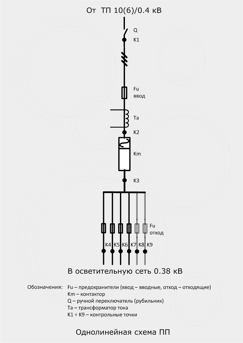
5.3 FS controller must ensure: 1) activation and deactivation of FS phase contactors, 2) control and fixation of presence and absence of voltages in FS control points (refer to single-line FS diagram on page 7 of this document), 3) control and fixation presence and absence of extraneous voltage on phases of FS lead-out feeders, 4) control and fixation of opening and closing of FS door and compartment door of FS special equipment, 5) control of signaling siren for FS door opening.
5.4 FS controller must have following technical characteristics: 1) supply voltage of 85 – 440 V, 2) nominal frequency of 45 – 66 Hz, 3) active consumed power of not more than 24 watt, 4) permissible input voltages of 0 – 440 V, 5) maximum current control of phase contactors of 3 A, 6) maximum current control of emergency signaling siren of 300 mA, 7) range of operating temperatures of -40 °C – +50 °C, 8) service life period not less than 20 years, 9) protection class (degree) of IP51.